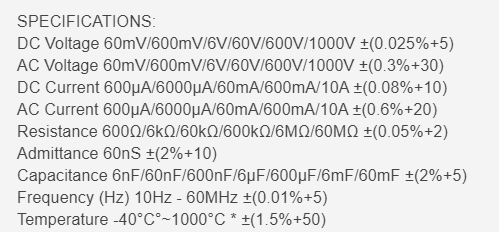
Several years ago I purchased the Uni-T UT 181A multimeter to replace the crusty off-brand multimeter which was beginning to fail and give erroneous readings. The main factor driving my decision was the extensive multimeter spreadsheet featured on the EEVBlog Forums. As the data shows it seems to be better spec’d than most the meters in similar price ranges. The biggest downside was the fact that it was UNI-T branded who are a somewhat unproven Chinese based company at least at the time of purchase in 2014.
The UT181A is UNI-T’s top end model and the specs are outstanding at least on paper. The input protection looks solid; there’s a large 1000V rated HRC fuse, plenty of MOVs and PTC’s and the 3.5″ TFT screen is a lot easier on the eyes than the classic monochrome LCD displays.
Unfortunately it has some quirks, the biggest being there seems to be almost no active support and therefore no spare parts or firmware updates. That’s bad, because the battery is a 7.2V lithium-ion pack and once that goes I’ll be forced to adapt something else to it. I’ve also wanted to get a replacement selector switch for mine as I carelessly pushed a hot soldering iron into it and melted a soldering iron tip-sized void into it.
The biggest issue right now is with how my unit has failed, or at least partially failed on me. The first failure mode actually happened to on two separate occasions, the first of which being when I had dropped the meter onto my workroom floor causing it to land on a thin area-mat over laminate flooring. The meter itself is mostly encased in rubber for events such as this, but upon inspection after the drop there was an issue. No matter what setting it was on the meter complained that the positive input lead was not connected properly when it most certainly was.
I was quick to disassemble it and found that an 0402 resistor (R5) had broken away from its pad on one end and was sticking almost straight up. I soldered it back down and viola, back in business.
A couple of years later a similar incident occurred but this time it was an adjacent resistor R4 which sheared off its pads. Again, a simple re-soldering was all that was needed to repair it.
The other problem I’m facing and the purpose of this post is a bit more tricky. Upon power up and while set to the Resistance setting, the meter would read maybe 10Meg and slowly drift down settling at around 3Meg after a few minutes. I lived with the issue until I had to measure some >3Meg ohm sources and decided to figure out what was causing it.
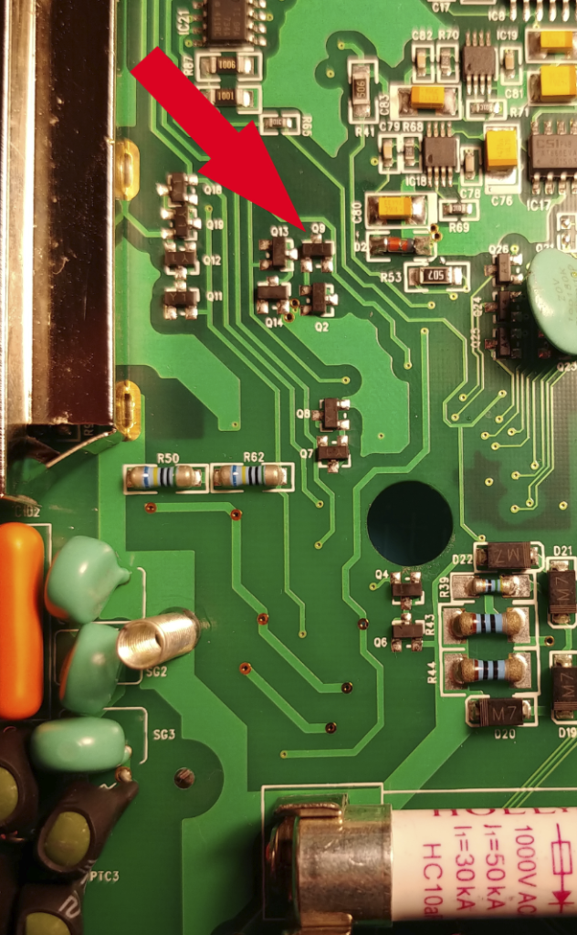
Due to the way the resistance reading drifted gave me a hunch that it was temperature related. I started by applying heat to parts of the main PCB while it was set to read resistance and found some promising results: If I applied heat to a specific area of the board, the reading would drop from a few mega ohms to high kilo ohms. I moved the heat gun around and around until I was certain of the general area of the fault might be.
Once I was certain I started the task of reverse-engineering the schematic since there are none available to me. In the area of interest, there are several transistors arranged back to back acting as zener-diodes for input protection as shown below:
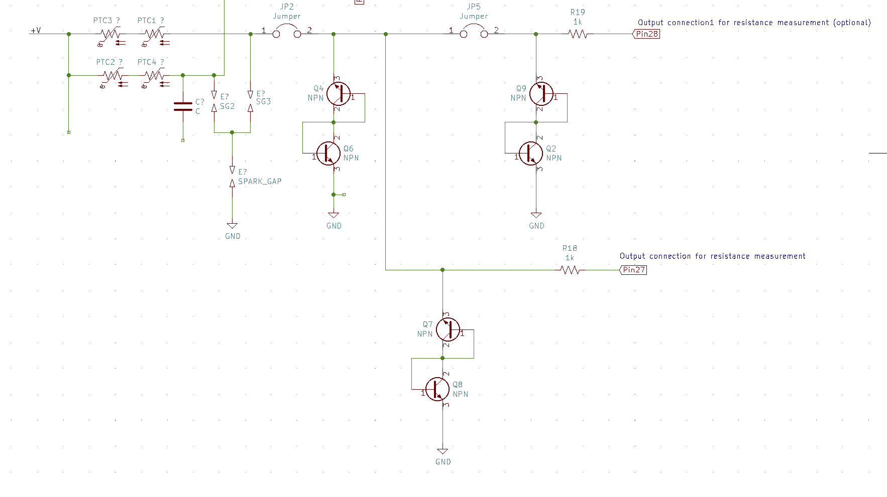
Pairs Q4/Q6, Q9/Q2 and Q7/Q8 are all acting as input protection for the Resistance setting. Since it was clear something was pulling the input low and causing the meter to read its own fault, I simply read the resistance across each transistor and found Q9 to be reading much lower than the others. As a quick check I removed it, powered the meter back and up and sure enough the issue was gone. It now read OL on the Resistance setting with the leads open as it is supposed to.
hi
any one having issues with the lcd screen?
I got a blue line on my screen for no apparent reason
anyone knows where to get the screens?
Same here on my side.
Happened long time ago, but it is beginning to annoy me.
Seems like we can find them on aliexpress : https://a.aliexpress.com/_EQrtI7j
Cost some 50€, but at least they are available somewhere.
I just don’t know if it fits into a connector or if we have to solder the ribbon cable.
Dear Admin,
thanks a lot for this interesting report on the UT181a. I’m about to purchase one of these units for my own. At least on eevblog there are lots of discussions about the input protection of this meter. I’m thinking about whether it might be possible to improve this section a little bit. I saw from your article that you have at least parts of the schematics of the meter. Did you (revers) engineer that by your own ? Would it be possible to make it open to the public ?
Many thanks for your reply,
Stefan
Thanks for commenting and apologies for the very dated reply. I did reverse engineer that part of the PCB personally and if anyone wants to use it for their own use they are free to do so. Crediting my site would be a bonus but I can’t enforce anything. I’m certain the input protection could be improved. It may be something I look into in the future, but currently it’s not a priority for me. I’ve seen the videos on YouTube from Joe Smith blowing the input protection on this meter with the barbecue igniter and while it is disappointing, I’ve been using and abusing this meter for the last 6 years and haven’t had any issues with it.
Great article and thanks for sharing. I would like to get this multimeter but I came across a YouTube channel stating that the multimeter failed to recognize input leads after a few uses. It just shows the lead error on every mode except for charging, mA, A.
Have you come across this issue or if possible share the input leads detection circuit.
Regards
Dani
Hi Dani, I briefly mentioned a similar issue about the same issue with this multimeter. It happened to mine twice each time after dropping it. The issue was resistors R4 and later R5 became dislodged from the PCB after the impact. They’re part of the lead detection circuit. Soldering them back in resolved the issue.
I had the lead error problem. It was marginal as if the photodiode path was being blocked by the plastic just a little bit more than it should be, maybe through insertion wear scuffing the transparent plastic area. It was the mA socket causing the lead error problem. I decided to swap around the two black opto diodes for the mA and A detect circuits figuring they would both have slightly different characteristics and perhaps the ‘A’ diode would give me a little bit more signal. It worked! Now both sockets detect the probe. It’s always possible that the very slight change in position when swapping the diodes might have contributed to a slight decrease in path loss too. Who knows. It was a quick fix and it’s working 🙂
Hello there.
I have a 2017 unit 181a
I got the lead error.msg a few years ago.
I came across this post and thanks to it i was able to bring it back to life.
It was a loose resistor. I soldered it and voila.
Thank you very much, saved a few hundred bucks there.
Alec
I’m glad my post able to help!