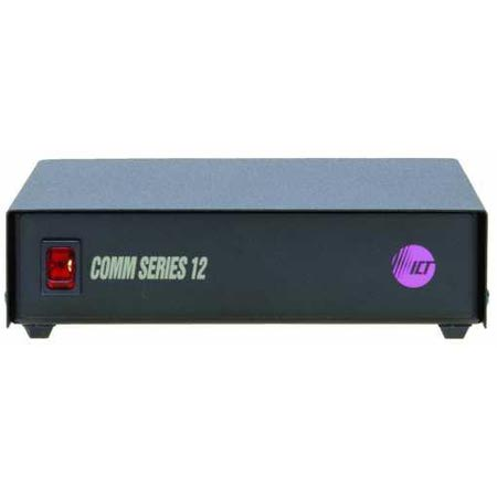
This project spawned from the acquisition of an ICT branded 12V, 10A non-adjustable power supply. It had lived its life powering some device in a supermarket and made its way into my workshop. I had needed an adjustable bench supply, and the schematic was readily available for a similar model which I have attached to this post, so I used it as a learning project to understand how analog voltage and current control worked, and how it could be modified into an adjustable supply.
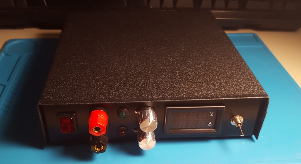
I won’t go into great detail about this project, but some of the features include: Current and voltage control from 0V to 20V, 0A to 10A with current limit and voltage limit indication LEDs, soft output switching, full earth isolation, automatic fan control, and voltage and current readouts via a cheapo panel meter from eBay. What about the ripple and noise? The line and load regulation? Any specs at all? Who knows! I made this before I had a digital scope and I can online imagine the state of the output waveform at low voltages and high currents, but despite being crude and needing repairs a couple times, it has helped power many a project for me.
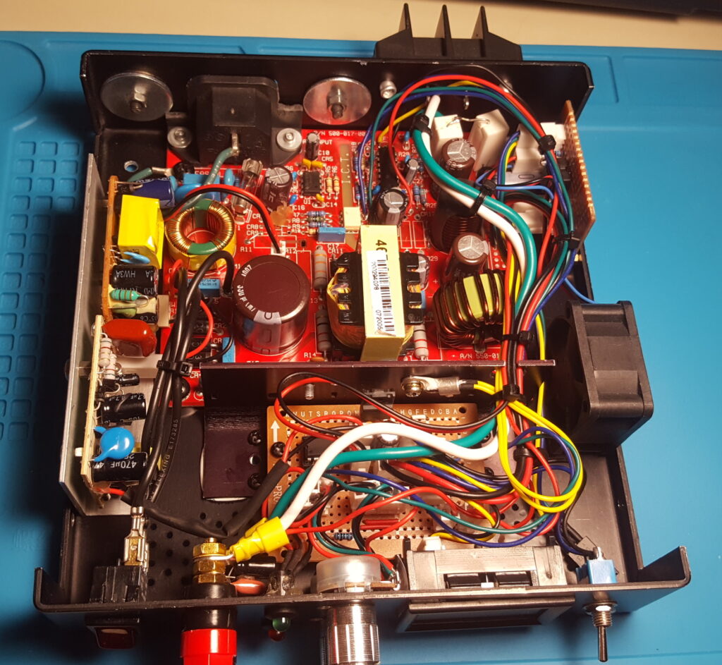
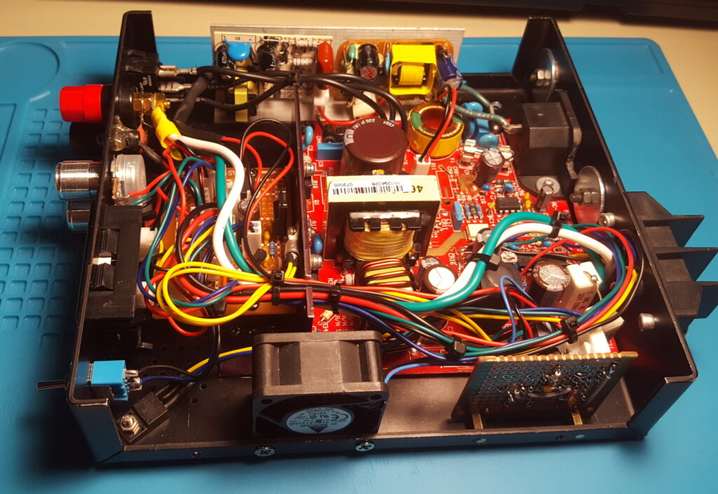
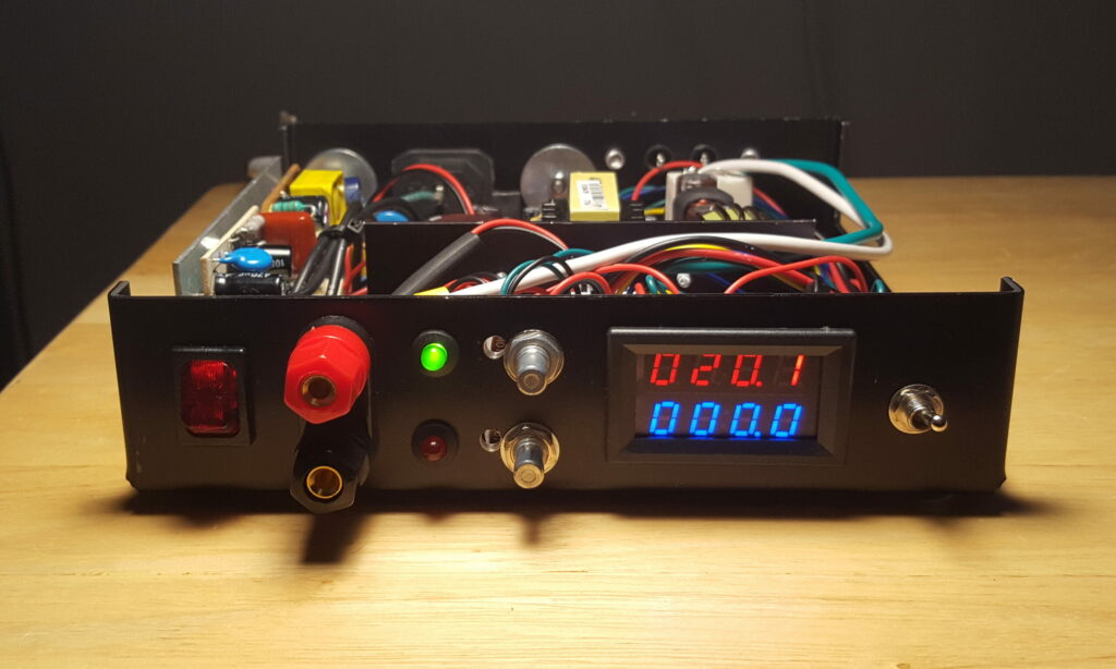
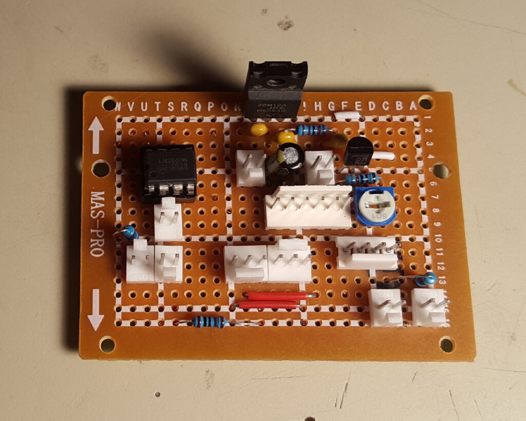
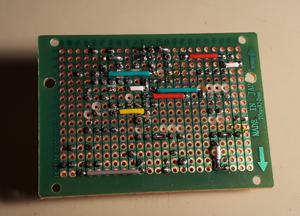
One challenge in modifying a power supply like this is that the circuitry which sets the output voltage is also powered by the output voltage, meaning if you drop the output voltage below a certain threshold, the power supply just stops working entirely. I had a healthy collection of phone chargers and wall wart supplies and scavenged a couple to work as auxiliary supplies to keep the necessary circuits powered full-time.
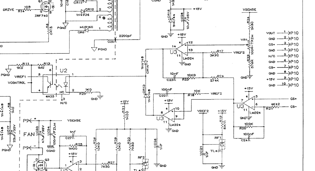
The way the voltage and current in this supply work are through a feedback loop. A few op-amps compare the output voltage and output current to a set level, VREF2, and drive an opto-coupler which in turn changes the duty cycle of a switch mode controller, UC3845, which results in voltage changes at the output completing the loop.
The voltage control works by dividing the output voltage down to some ratio, where 12V_out = 2.5V_divided, and comparing it to an adjustable reference via an op-amp. The reference level is set by one of the front mounted potentiometers. In the schematic below, op-amp U3 (pins 12, 13, 14) compares the divided output voltage from VR1 with VREF2. By making VREF2 adjustable from 0V to 2.5V, the output voltage will follow from 0 to 12V.
The current control works by amplifying the tiny voltage drop across a current shunt, so that 10A = 2.5V, and comparing it to an adjustable reference via an op amp. The reference level is set by the other front mounted potentiometer. In the schematic below, op-amp U3 (pins 5, 6, 7) first amplifies the voltage across a current shunt, then compare it with VREF2 using another op-amp. By making VREF2 adjustable from 0V to 2.5V, the output current will follow from 0A to 10A.
Each op-amp feeds a diode which share a cathode, and in turn feeds an opto-coupler. The opto-coupler feeds the input of a switchmode controller IC, which changes the output voltage of the power supply by adjusting the duty cycle of the switching transistors. By using diodes like this, whichever reference is set higher, be it the current or voltage reference, will be the set limit of the supply. The diode with the lower anode voltage removes itself from the feedback loop.
