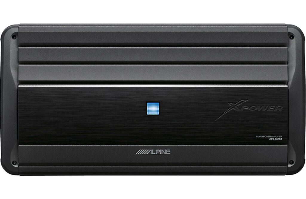
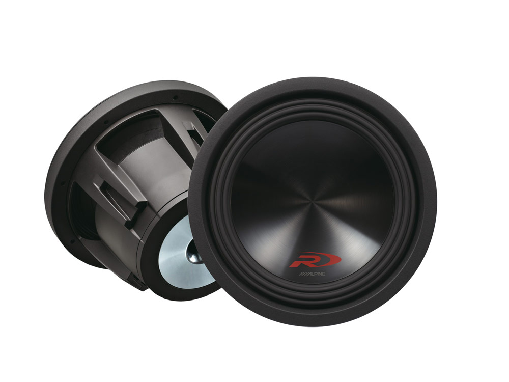
A customer came to me wanting a custom sub box to fit into the back of his old Chevy Blazer. He had three Alpine SWR-10D2 subwoofers and and an Alpine MRX-M240 mono amp which is spec’d to output 2400W into 2 ohms.
Finding Maximum Power Per Driver
One of the first steps is calculating the best way to wire them together. Each sub has twin 2-ohm voice coils rated allegedly for 500W a piece. The amplifier has the following specs:
\(1000W @ 1\Omega \)
\(2400W @ 2\Omega\)
\(1500W @ 4\Omega\)
Which, when plotted, looks like this:
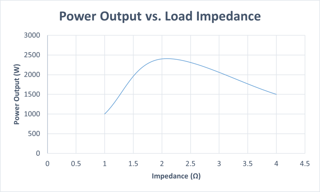
The power output peaks at 2 ohms, so we want to keep our combined sub impedance close to that value. There’s basically two practical ways to wire them; series-parallel or parallel-series. Wiring everything in parallel would result in \(1\Omega || 1\Omega || 1\Omega = 0.33\Omega\) which is far too low. Wiring everything in series would result in \(4\Omega + 4\Omega + 4\Omega = 12\Omega\) which is far too high, so there must be some combination between these two that will work.
Let’s try voice coil in series, and each driver in parallel. That looks something like \(4\Omega || 4\Omega || 4\Omega = 1.33\Omega\) which is close. Let’s try the other way around, each coil in parallel and each driver in series: \(1\Omega + 1\Omega + 1\Omega = 3\Omega\). While it is further from 2Ω than 1.33Ω, the plot tapers off more gradually at higher impedances meaning we actually get more power output at 3Ω than 1.33Ω.
Reading from the graph, it looks to be about 2000W @ 3Ω. If we divide the 2000W by 3 we get 667W per driver, or 333W per voice coil.
While we’re at it we can calculate a suitable wire gauge to use. Knowing power and resistance, we can calculate current using:
\[P = I^2 R\]
\[I = \sqrt{\frac{P}{R}}\]
\[I = \sqrt{\frac{2000W}{3\Omega}}\]
\[I = 25.8A_{rms}\]
Using the below chart, we can estimate what gauge of wire to use by looking at the “Maximum amps for chassis wiring” column. This value refers to a single wire in free air, vs “Maximum amps for power transmission”, which refers to bundles of wires together.
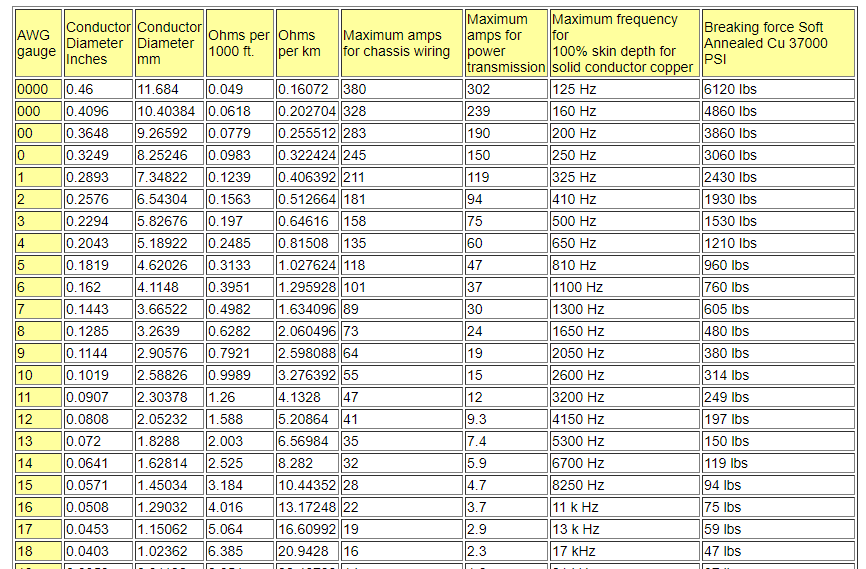
As low as 14 gauge will work, but 12 seems better. But since I like to make things a bit more robust I ordered 10′ of black and red 10AWG silicon insulated wire. I’ll probably need all 10′, so we can calculate the total power loss and voltage drop in the cable as follows:
\[R= \frac{0.9989\Omega}{1000ft}20ft\]
\[R = 0.02\Omega \]
Total voltage drop is:
\[V = IR\]
\[V_{drop} = (25.5A_{rms}) (0.02\Omega)\]
\[V_{drop} = 0.509V_{rms}\]
And lastly the power loss is:
\[P_{loss} = (0.509V_{rms}) (25.5A_{rms})\]
\[P_{loss} = 13W\]
Both these values are completely reasonable for what we’re doing here.
Ported vs. Sealed Enclosure
The previous post on subwoofer design covers all the pros and cons and calculations related to determining what kind of box to go with but I’ll run through some here. First we calculate EBP:
\[EBP = \frac{fs}{Q_es}\]
\[EBP = \frac{31\text{Hz}}{0.54}\]
\[EBP = 57.4\text{Hz}\]
This EBP is low, but still above the minimum recommend EBP for a sealed enclosure, so for the sake of SPL and booming bass we’re going with a ported one.
Next up is our volume calculation:
\[V_b = 20 {Q_{ts}}^{3.3} V_{as}\]
\[V_b = 20 {0.51}^{3.3} 18L\]
\[V_b = 39L\]
With 3 drivers in mind:
\[V_b = 117L\]
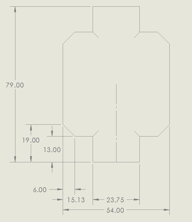
This is a fairly hefty volume. We’re constrained mostly by one dimension; the width of the cargo area of the SUV which is 49″. The height of the box was also wanted to be kept fairly low. I decided to make it 47″ to leave barely enough room to get your fingers by it. Using 3/4″ MDF, this gives us an internal width of 45.5″. I set the internal height and depth to 10.5″ and 15.5″ respectively. This resulted in a total volume of 121L, which is slightly oversized, as the volume of the ports, drivers and bracing will lower this slightly.
Port Calculations
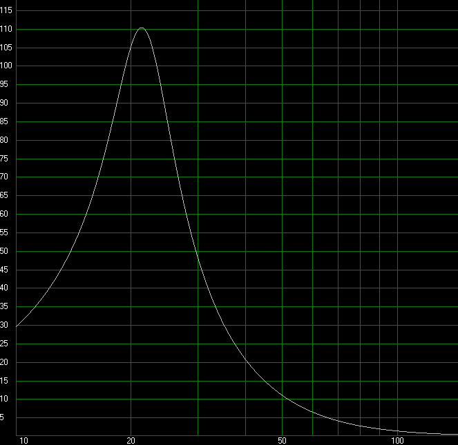
This is where I’ll be using WinISD Pro to do the grunt work in. You put in the driver’s specs, number of drivers, power input, then play around with the port diameter, number of ports, and air velocity until you get something you can actually build. I decided on 2 ports of 3″ diameter, 14″ loing which put the tuning frequency at 24Hz. Below is a plot of the airspeed at maximum power. Maximum flow is 103.8m/s @ 24Hz which is 0.3 mach. It’s rather high, above the 0.2 max guideline, but the ports will have large flanges on both ends so I’m not overly worried about port noise.
Port materials were all ordered from https://solen.ca/ which is my favorite place to get speakers and speaker components. Parts Express used to be my go to, but duty and shipping outweigh the benefits of the larger selection.
We can also calculate the volume of the ports, which works out to be 3.2L total. So our 121L enclosure ends up being 117.8L which is closer to our calculated value.
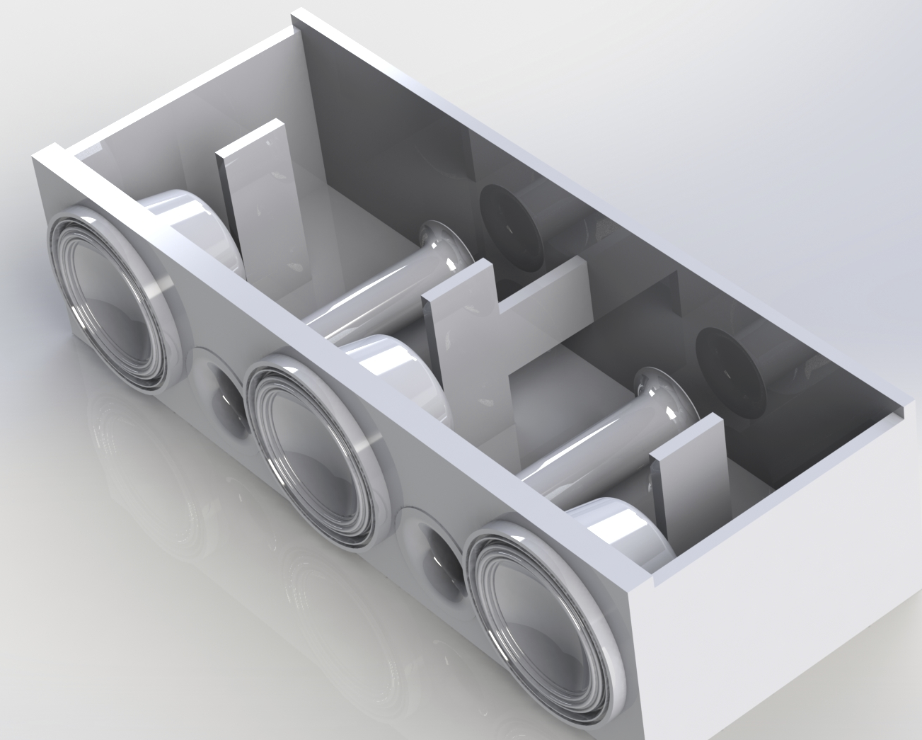
Construction
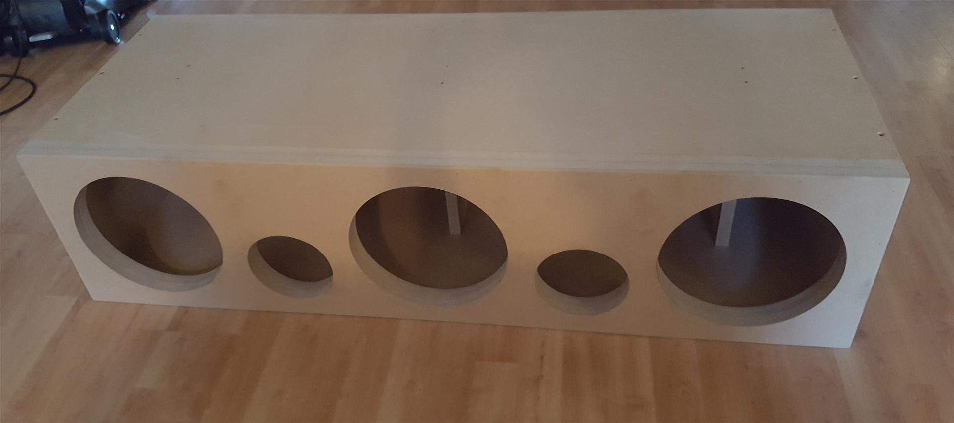
The enclosure is a fairly a simple design. Just a big rectangle with some holes cut in it. Bracing is simple, with the most being applied to the upper and lower panels as they have the most unsupported area. The front is two sheets of 3/4″ MDF to add rigidity seeing as 5 gaping holes were going to be cut into it. I modeled the box, speakers and ports in CAD to check dimensions and sent the prints off to get assembled. Originally me and the customer were going to do all the labor on the enclosure but he decided to just get it built by a 3rd party as I’m currently not setup with a woodshop. Below are a couple renders and the final product:
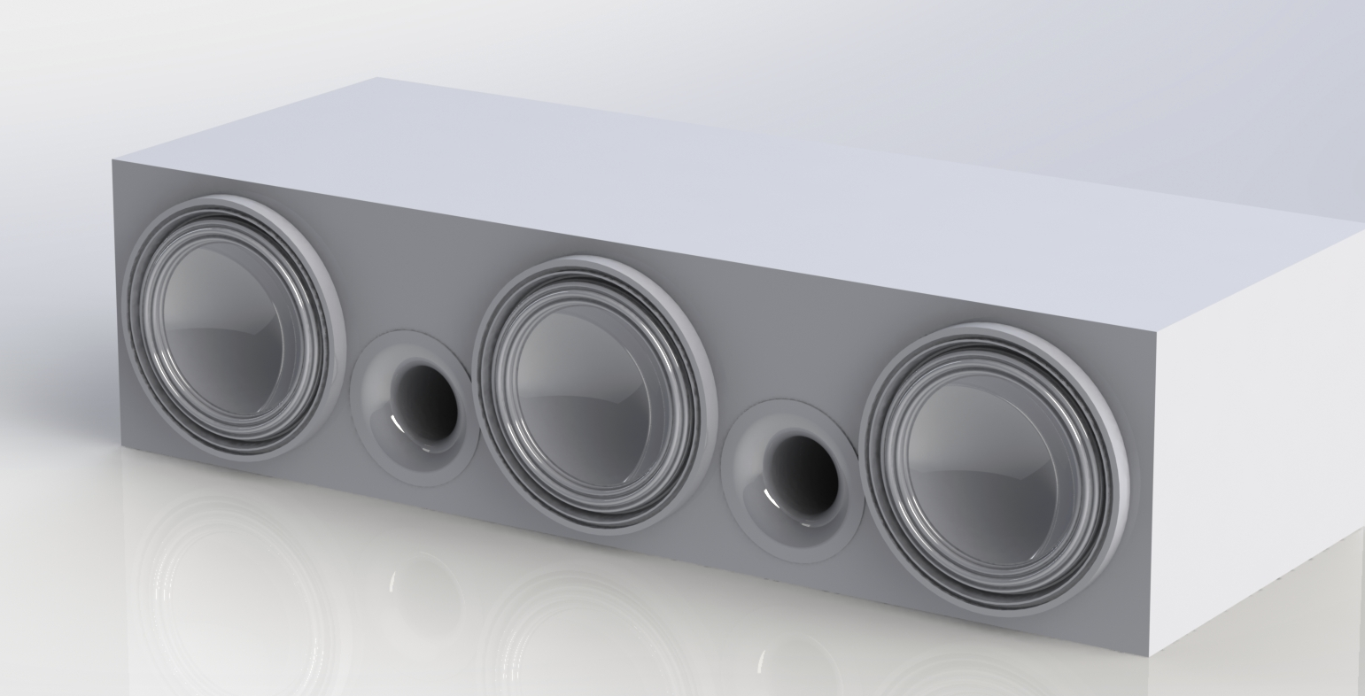
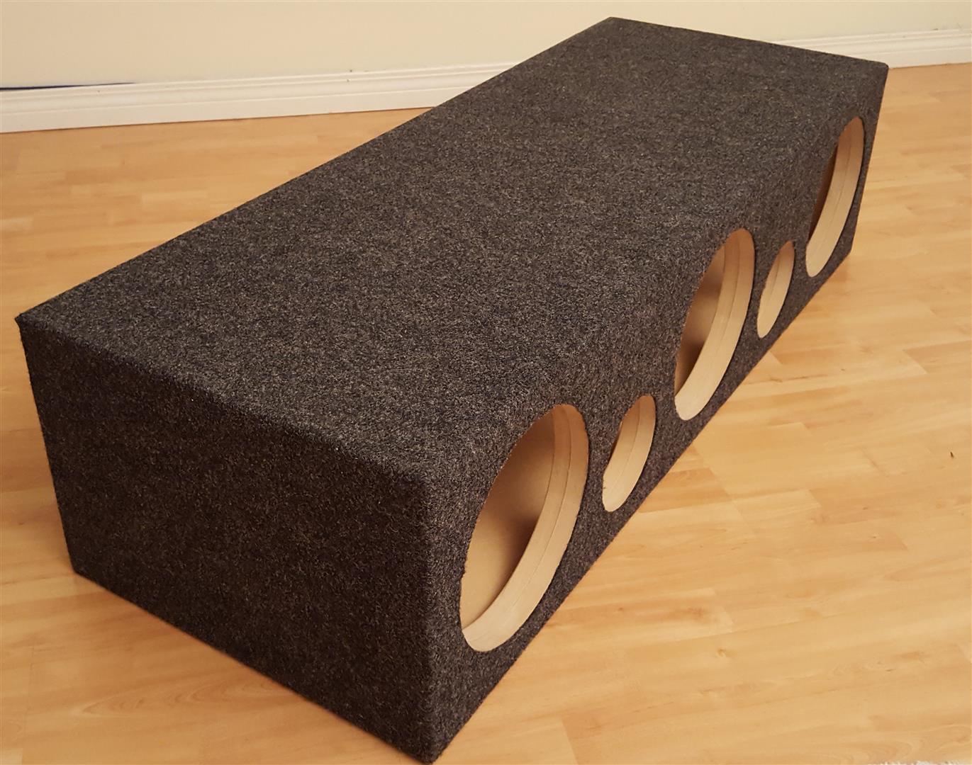
Shiny. All that was to left was to wait for the cabinet to arrive.
Finishing the Box
It arrived exactly as it was drawn. The guys who built it did a really nice job. The next step was figuring out how to carpet it. The long side of the box required 118″ of carpet while the short side required 59.5″. I ended up ordering this Metra Box Carpet which came as a 54″ x 180″ sheet. This meant I would have a gap on the bottom which would need to be filled, which you will see later. Also very importantly, I ordered a can of 3M Super 77 spray adhesive which was recommend by various people who had carpeted their own boxes. It worked very well in this application.
Basic Car Audio Electronics is an incredibly useful site with all kinds of audio and electronic related tutorials, including a carpeting tutorial with some very easy to understand illustrations. Ideally, what I would have done with this box is recessed both ends and made up some carpeted false panels to cover the seams. I changed the design to reflect this, but the box had been built before me or the customer even realized it. This meant I would have to find another way to finish the ends.
I used a CAD program to make a cut and fold guide to follow as well. The top and bottom were initially just squares of fabric I was just going to fold over itself and staple, but I realized it wasn’t going to look very good, so I ended up taking a more complicated approach as will be seen.
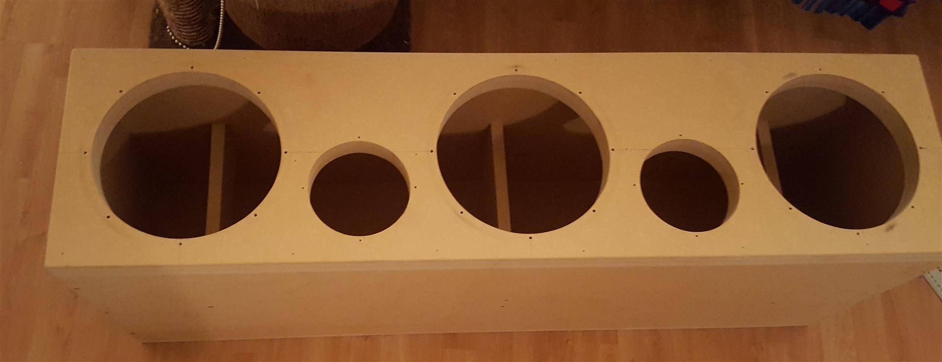
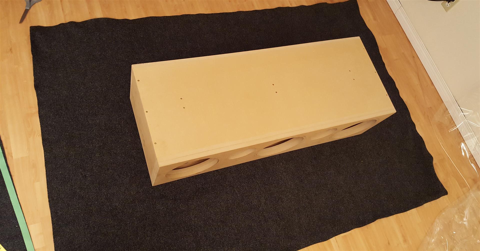
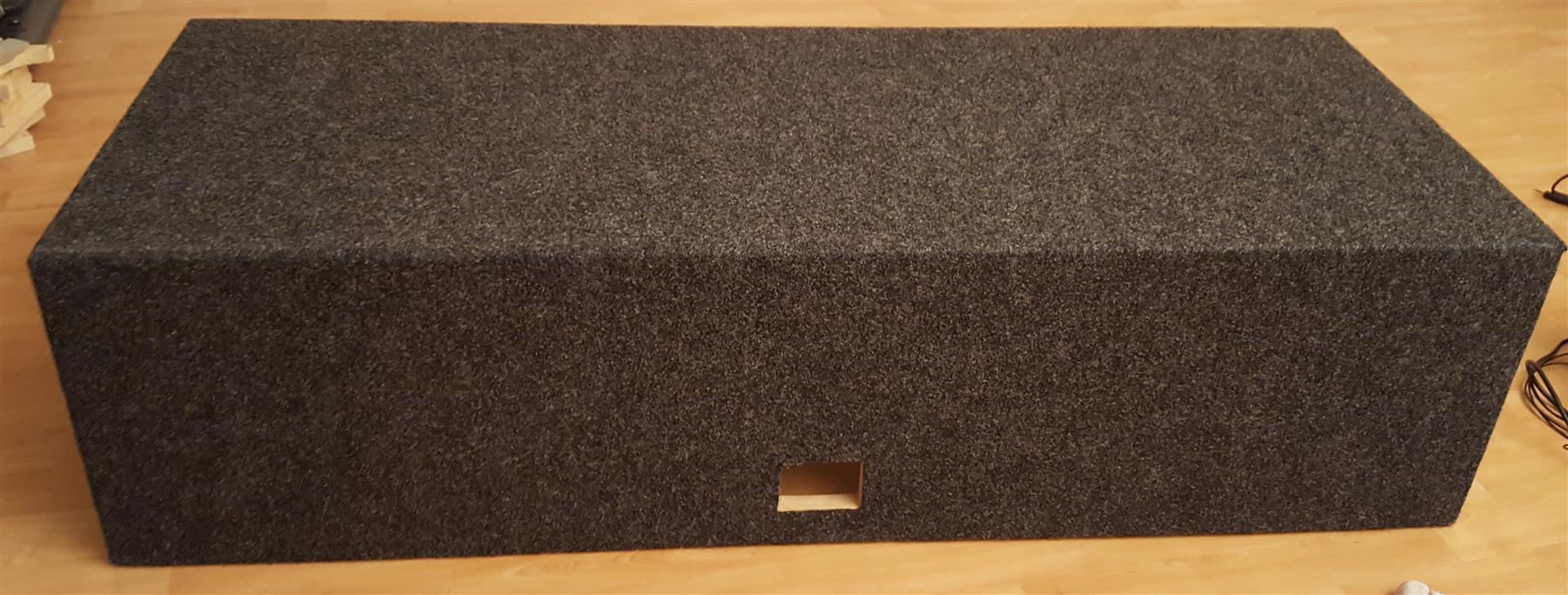
The raw box exactly as it came to me:
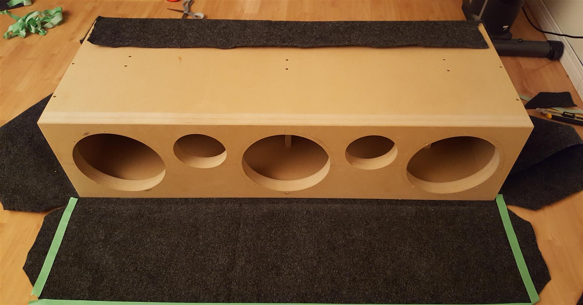
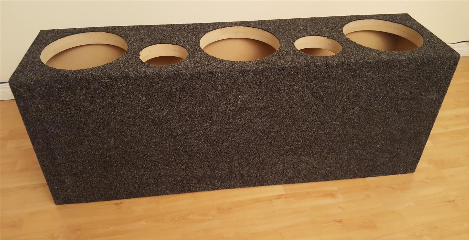
Pre drilled the holes for the flanges and woofers:
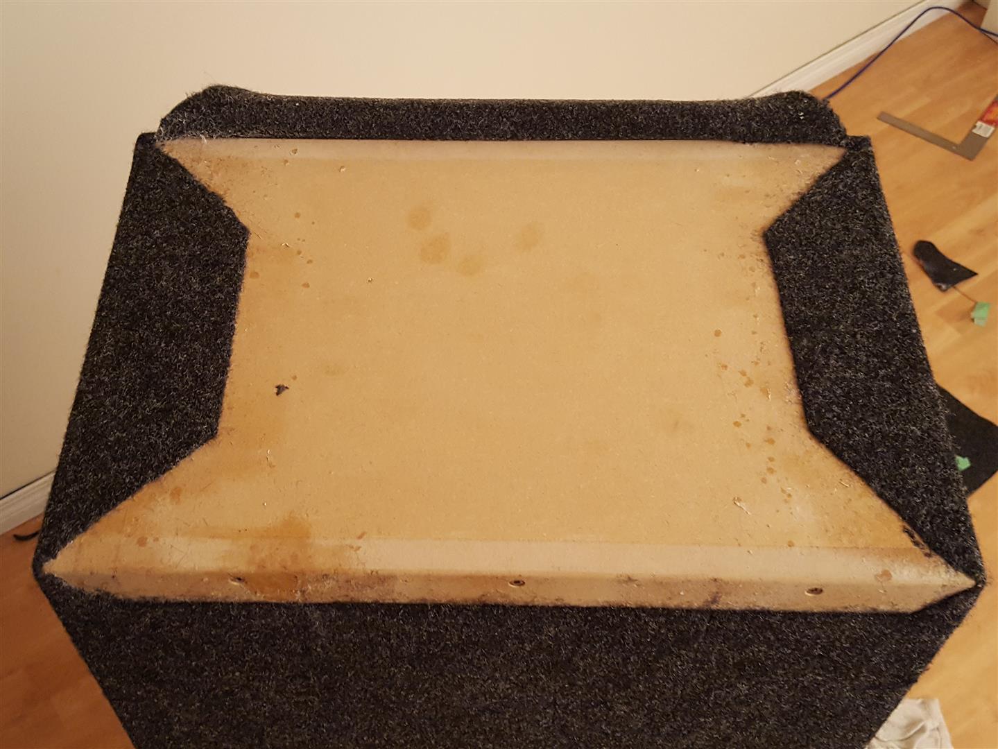
The first step was to cut the carpet down from its 180″ length to 79″. I used a piece of masking tape as a guide and a long straight edge, tape measure and square to align the tape. The box is then centered about the cut piece, and placed top side down so the seams end up on the bottom.
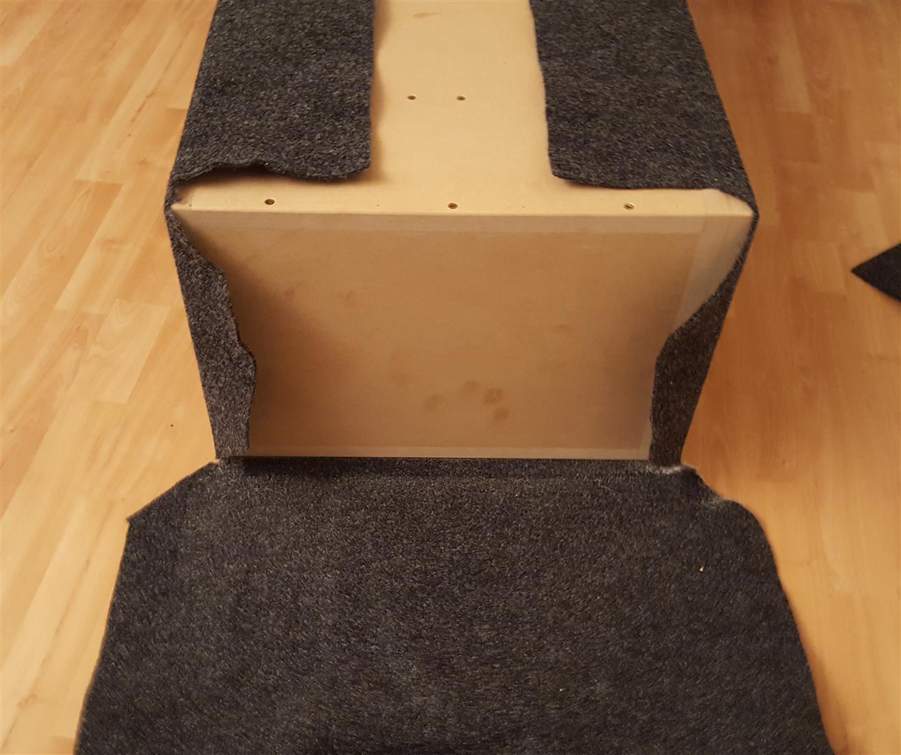
Here I’ve cut the edges out through carefully measuring and marking using more masking tape. I have the rear and top panels adhered already. The spray adhesive is very nasty toxic stuff so I wore a respirator and had a fan placed at a window to exhaust the fumes. It’s also probably best to wear an old long sleeved shirt, as my bare arms ended up covered in sticky over spray.
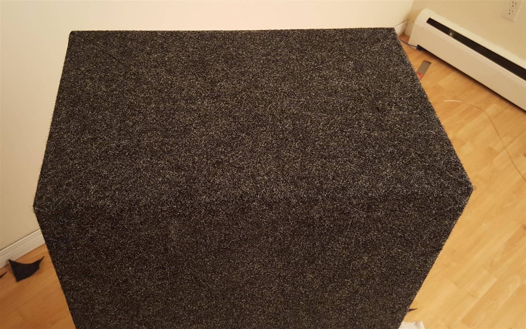
The procedure I used to adhere the carpet was as follows: First, mark out the area you’re going to to spray with masking tape, since you spray both the carpet and the box, not just one or the other. This allows you to concentrate your spray within the boundaries so as not to get adhesive all over pieces of carpet that aren’t ready to be adhered. Once you spray the box and carpet liberally, pivot the entire box upward so the panel you’re gluing ends up facing the floor. Once they make contact, you can pivot the box back down so the adhered panel is facing you again. Now you can check for any wrinkles or oddities and pull the carpet flush as needed. I didn’t have any problems with wrinkles but the carpet and glue has some give before it cures so you can make changes as needed.
Next came the edges. Like I mentioned, I was going to just fold the carpet up and staple it, but on doing a mock up, it just didn’t look good. So my only option left was to carefully cut the edges and make all the seams align flush. It was daunting, but as it turns out, the carpet has a lot of stretch. Combined with the initial tackiness of the glue, you can push and prod and stretch your seams to make them look, well, seamless:
But before that, I decided to finish the bottom seams. Get some practice where no one can see before working on the edges. As can be seen in the previous image there was a sizable gap that needed filling. The procedure to fill it and get a straight seam is pretty simple. All you do is glue the edge piece and your filler piece down so they overlap. Then you run a razor against a straightedge along where you want the seam to appear. Next, peel away any overlapping pieces carpet, and you’re left with a perfect seam with minimal work.
Also I had cut the holes out for the speakers here. I just used a fresh razor blade, pierced it through the opening, then used the edge of the hole to guide the blade. Speaker carpet cuts very clean, its a lot easier to work with than one may think:
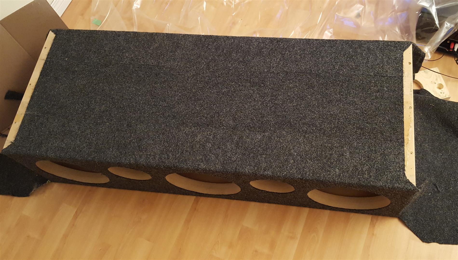
Here’ I’ve adhered everything but the side pieces which are the most complicated. My strategy for this was just to fold the flap from the rear over this area, then carefully cut it as to follow the seams of the pieces that are already glued.
The final outcome was better than I had expected. Following the seams wasn’t too hard, and if you went off a bit, it was easy to stretch the carpet a little to fill the void.
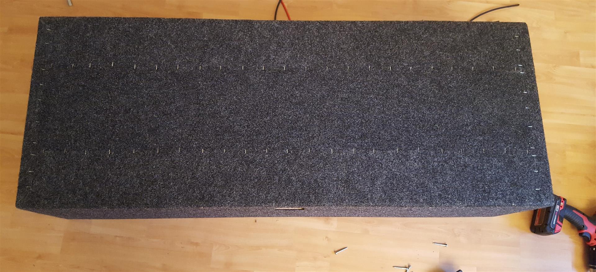
Lastly I stapled the seams along the bottom for reassurance. It’s going to be pushed and dragged around and I don’t want them coming undone anytime soon:
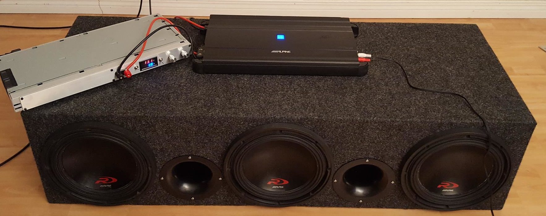
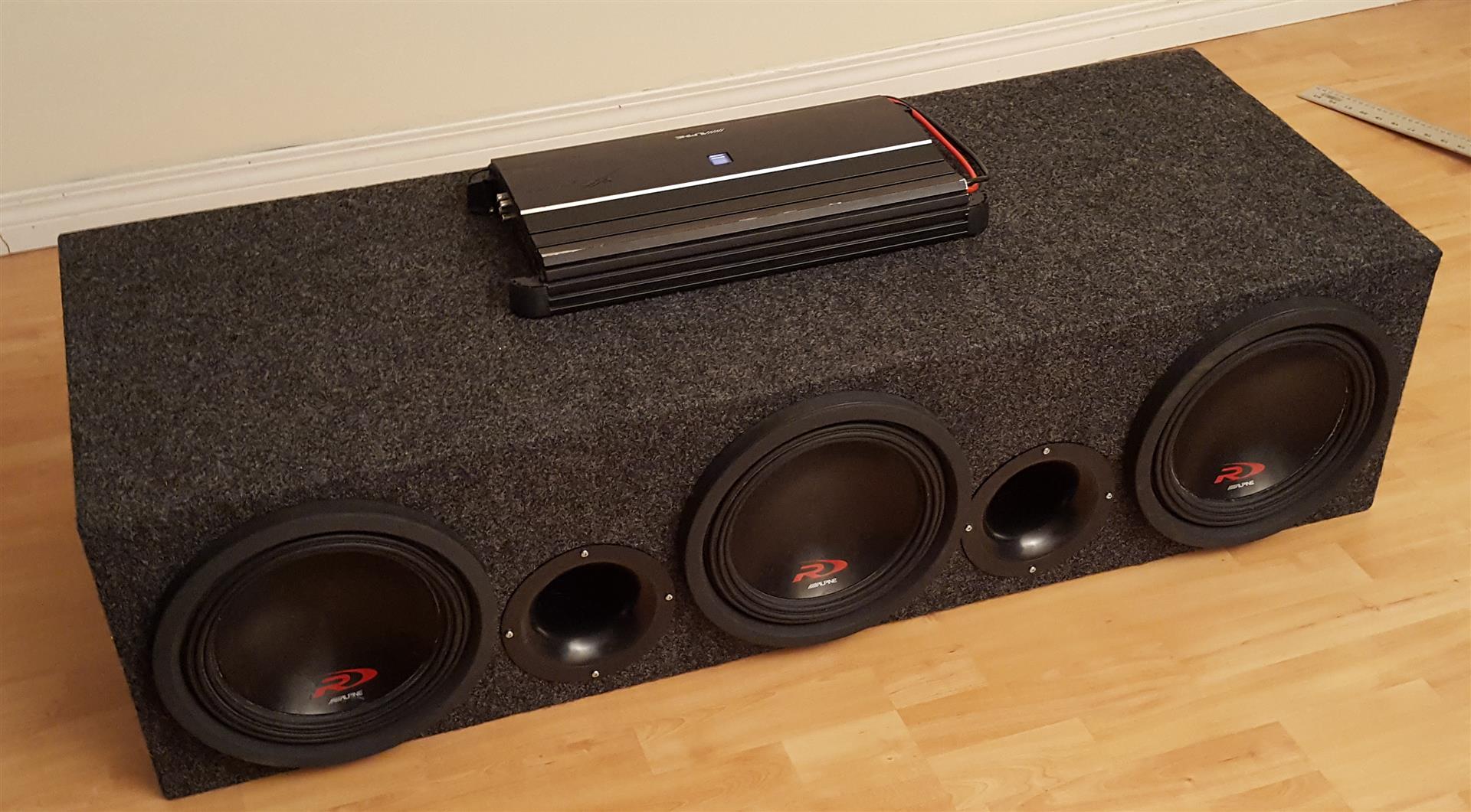
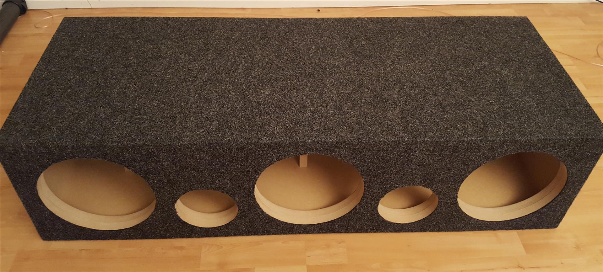
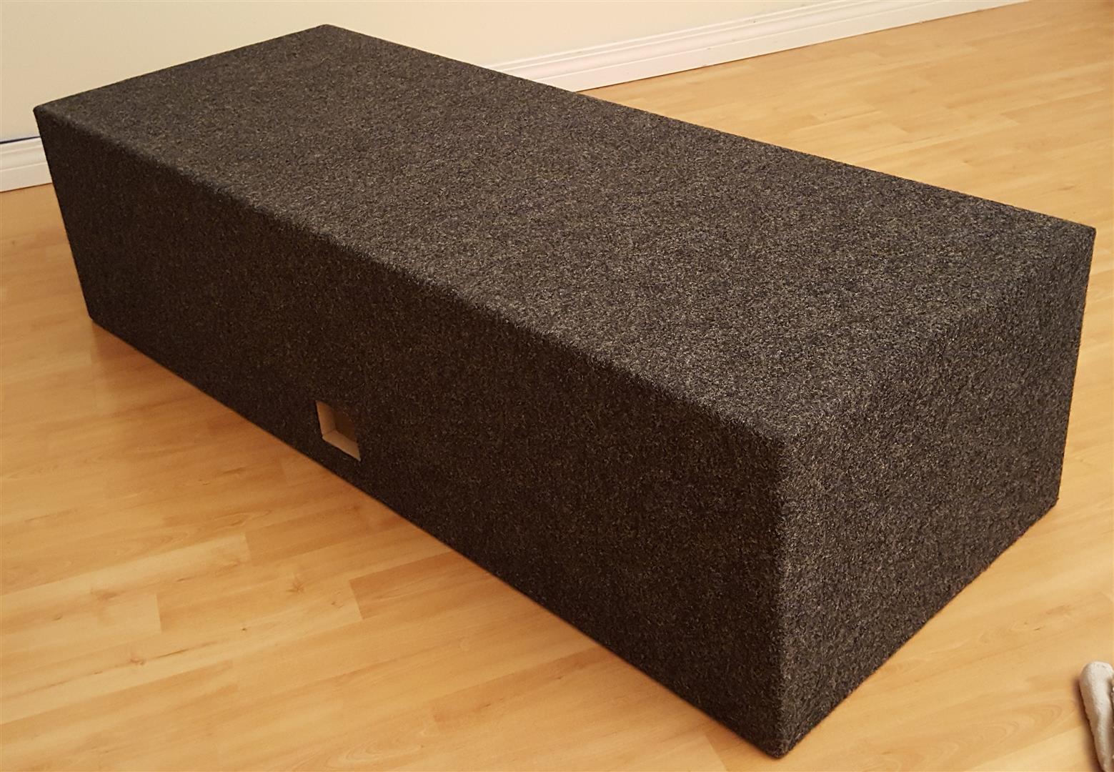
And time for some beauty shots:
All that was left was to add the interior dampening, which was 1″ thick memory foam, wire the subs in and test:
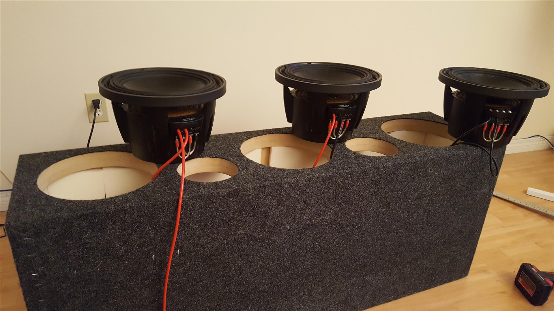
The power supply is one I made, which will be featured in another post soon. It’s not quite finished in this picture but it’s enough to test the amp and subs: